Building a DIY head-mounted gaze tracking camera
For a few years I've been tinkering with a project surrounding tracking biometrics against video game play. This led me down the path of wanting accurate gaze tracking, with the goal of overlaying a heatmap of eye movement on captured gameplay to augment a stream for example, or help UI designers/researchers create better interfaces.
Note: This post was originally drafted in April, 2015.
After some research, I discovered that Tobii has pretty much run the show on gaze tracking tech for a long time, and for most of the early 2000s (really up until 2015/2016) this tech was prohibitively expensive for consumer use. At the time (March, 2015), there wasn't a consumer option readily available in a price I could afford, and I came across this paper from the West Pomeranian University of Technology in Szczecin suggesting that it is possible to build a workable, pupil-based eye tracker out of a webcam and a few infrared diodes.
This sounded a lot more fun to me than shelling out the cash for a pro level gaze tracking camera, and I had an old web cam that I had been looking for a reason to tear apart (that thing had been talking shit for months).
Thankfully, Michal Kowalik, one of the authors of aforementioned paper, had also published a a great tutorial on how to build a DIY tracker.
Building a DIY Gaze Tracker (and why maybe you shouldn't)
TL;DR: DIY Gaze tracking is a fun project but there are consumer level eye trackers that are nearly as cheap and considerably better. I'll mention a few in the conclusion. If you're set on building your own, I recommend following Kowalik's tutorial - but I'll give an overview of the process so you know what you're getting into.
Step 1: Find a webcam you hate and gather other supplies.
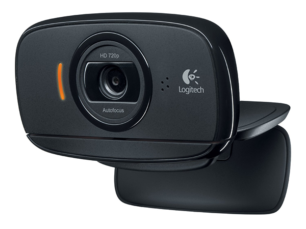
The build outlined in the paper uses a Microsoft LifeCam VX-1000, but I used a Logitech C525 (pictured). The other important things you'll need are three IR LEDs, one 1/4W 22 ohm resistor, and some negative film OR if you don't have access to any negative film, I was able to use the interior of a 3.5" floppy disk. (I realize both of these things are equally archaic, but for it was easier for me to find a floppy disk than negative film.) You'll also want some sort of glasses frame, you can pop the lenses out of some old sunglasses or buy some safety glasses, but you'll want to remove the lenses, and pick up some low gauge aluminum craft wire for mounting the whole thing to the glasses frame.
One important note about the resistor, you're looking for 22 ohm, not the considerably more common 22k ohm. Your goal is to illuminate the LEDs off of a USB power rail, so 22k ohm's would obliterate the current. I found some on Amazon, but the listing appears to be gone now.
Step 2: Replace the webcam's visible light filter with your DIY IR filter
Your webcam will likely have a visible light filter. The goal is to remove this, and replace it with a DIY IR filter, that you're going to make from either your negative film or floppy disk. The first thing you'll need to do is pry the enclosure off the camera. If possible, try to keep some of the case in tact, because it'll come in handy for mounting later, but most of all just be sure to not damage the components. There's a good chance that someone out there has disassembled your camera model, so google around if you're having trouble cracking that egg.
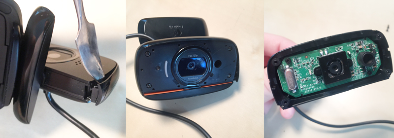
Now comes the tricky part, the filter you need to remove is likely on the underside of the lens, and I know that at least on the C525, getting to it meant completely destroying the auto-focus mechanism. If there is a cage over the lens, pry that off. The lens should be "floating" over the censor, but if your camera has an autofocus mechanism, it will be attached to the sides of the lens housing. I made a necessary sacrifice and clipped these wires to be able to pull the lens out.
The visible light filter should be a translucent pinkish piece of plastic or glass. I used a razor blade to remove this, but you may have luck with a heat gun to loosen the adhesive. Then, using the visible light filter as an example, cut a square out of your floppy disk or negative film and very carefully glue it in the place of the filter you removed. This is the most delicate part of the process, as you're working in very close proximity to the lens. You'll see in the photo on the right below, the lens filter replaced with a circular cutout from the floppy disk.
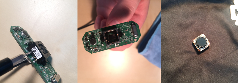
Once the glue dries, re-assemble the lens the best you can, replacing any cage you may have removed. You're almost done with the internals of this thing.
Step 3: Assemble and power your IR LED array.
The tutorial from the paper recommends powering the IR array off the USB power rail for the camera, but that was easier said than done on the C525, so I powered the LEDs using a separate USB cable. This just meant I had a little bit more wire and needed an extra USB port.
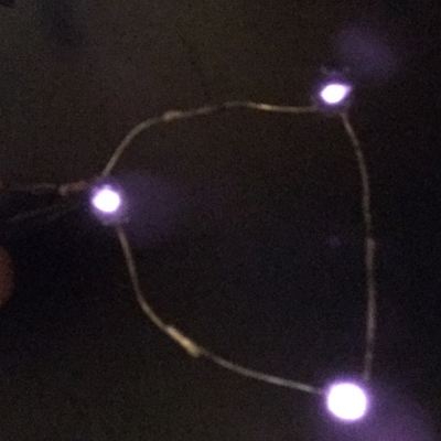
Solder the 3 IR LEDs together with the resistor as shown in Figure 4.1 in the PDF and power them using either off the power rail from your camera's USB cord, or a separate USB cord. Make sure you've got your resistor in the circuit so you don't accidentally cook your lights.
Once you've got your lights wired up, one easy way to check if they're working is by using the front-facing camera on an iPhone. I can't speak to other phones, but the iPhones rear camera has an IR filter, but the front-facing camera does not. If you hold the powered LEDs up to the camera, you should be able to see their light emitted on the phone's display.
Step 4: Re-assemble everything and try it out
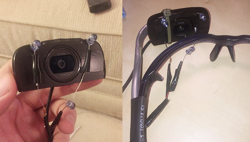
Once you've verified your IR is emitting, you can mount everything to the glasses frame and take it for a spin. ITU GazeTracker is the software I used and it allowed me to record a logfile of the input from the tracker. You may be able to download it from here though that link has been unreliable for me lately.
Pictured below is the assembled camera with the IR array attached.
Step 5: Buy a commercial gaze tracker because yours is not very good
I'm half kidding. Hopefully, at this point you've assembled an incredibly accurate, low cost gaze tracker using scraps! But, if you're anything like me, there's a good chance that your lens is out of focus, and the reliability of your newly built toy is not great. I was proud of what I made, but I wasn't entirely happy with the results - using ITU Gaze Tracker, it would frequently lose tracking, and the fidelity just wasn't as high as I wanted it to be. While I was building it, I had discovered The Eye Tribe - a company seeking to bring low cost eye tracking to the masses, and I ordered their original dev kit. They've since announced a second tracker, and Tobii has begun integrating eye tracking into some laptops. Steelseries is also now selling their Sentry Eye Tracker which runs on Tobii's new EyeX low-cost platform.
In conclusion, inexpensive eye tracking has come a long way since I started down this path. I've been using the original Eye Tribe SDK to record gaze input, and it's been considerably better than my DIY tracker, but I am also interested in checking out Tobii's latest advancements. If you have questions about any of this, feel free to reach out on twitter @jakelear.